RK3588 SPI
本文以mcp2518 spi转canfd为例
1.设备树配置
参考:https://forlinx-book.yuque.com/rh74yu/rkword/67f7103c0796b9430522f9240d15be74
2.驱动排查

2.1 可以看到芯片没有检测到,首先检查硬件的线接的是否正确,
一般spi主从机网络标号都是miso/mosi,这样丝印一样的接一块。如果是DI/DO这种的丝印则按照下图方式接线
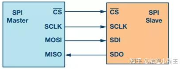
2.2 如果接线正确可以测量从机供电、时钟是否正常
2.3 以上都正确的话下一步可以测量波形
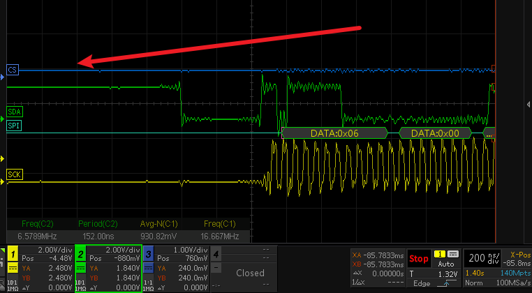
根据上面波形可以发现通信过程中片选没有被拉低,通过io工具测试该引脚已经被正确复用成片选功能
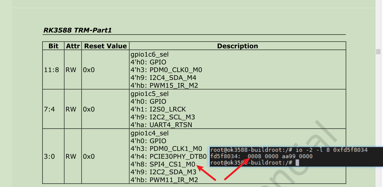
从驱动中找到片选置位的地方如下
static void spi_set_cs(struct spi_device *spi, bool enable, bool force)
{
	bool enable1 = enable;

	/*
	 * Avoid calling into the driver (or doing delays) if the chip select
	 * isn't actually changing from the last time this was called.
	 */
	if (!force && (spi->controller->last_cs_enable == enable) &&
	    (spi->controller->last_cs_mode_high == (spi->mode & SPI_CS_HIGH)))
		return;

	spi->controller->last_cs_enable = enable;
	spi->controller->last_cs_mode_high = spi->mode & SPI_CS_HIGH;

	if (!spi->controller->set_cs_timing) {
		if (enable1)
			spi_delay_exec(&spi->controller->cs_setup, NULL);
		else
			spi_delay_exec(&spi->controller->cs_hold, NULL);
	}

	if (spi->mode & SPI_CS_HIGH)
		enable = !enable;

	if (spi->cs_gpiod || gpio_is_valid(spi->cs_gpio)) {
		if (!(spi->mode & SPI_NO_CS)) {
			if (spi->cs_gpiod) {
				/*
				 * Historically ACPI has no means of the GPIO polarity and
				 * thus the SPISerialBus() resource defines it on the per-chip
				 * basis. In order to avoid a chain of negations, the GPIO
				 * polarity is considered being Active High. Even for the cases
				 * when _DSD() is involved (in the updated versions of ACPI)
				 * the GPIO CS polarity must be defined Active High to avoid
				 * ambiguity. That's why we use enable, that takes SPI_CS_HIGH
				 * into account.
				 */
				if (has_acpi_companion(&spi->dev))
					gpiod_set_value_cansleep(spi->cs_gpiod, !enable);
				else
					/* Polarity handled by GPIO library */
					gpiod_set_value_cansleep(spi->cs_gpiod, enable1);
			} else {
				/*
				 * invert the enable line, as active low is
				 * default for SPI.
				 */
				gpio_set_value_cansleep(spi->cs_gpio, !enable);
			}
		}
		/* Some SPI masters need both GPIO CS & slave_select */
		if ((spi->controller->flags & SPI_MASTER_GPIO_SS) &&
		    spi->controller->set_cs)
			spi->controller->set_cs(spi, !enable);
	} else if (spi->controller->set_cs) {
		spi->controller->set_cs(spi, !enable);
	}

	if (!spi->controller->set_cs_timing) {
		if (!enable1)
			spi_delay_exec(&spi->controller->cs_inactive, NULL);
	}
}
发现走原生片选分支会调用spi->controller->set_cs(spi, !enable);去控制片选。set_cs回调函数为rockchip_spi_set_cs;
ctlr->dev.of_node = pdev->dev.of_node;
	ctlr->bits_per_word_mask = SPI_BPW_MASK(16) | SPI_BPW_MASK(8) | SPI_BPW_MASK(4);
	ctlr->min_speed_hz = rs->freq / BAUDR_SCKDV_MAX;
	ctlr->max_speed_hz = min(rs->freq / BAUDR_SCKDV_MIN, MAX_SCLK_OUT);

	ctlr->setup = rockchip_spi_setup;
	ctlr->set_cs = rockchip_spi_set_cs;
	ctlr->transfer_one = rockchip_spi_transfer_one;
	ctlr->max_transfer_size = rockchip_spi_max_transfer_size;
	ctlr->handle_err = rockchip_spi_handle_err;

	ctlr->dma_tx = dma_request_chan(rs->dev, "tx");
	if (IS_ERR(ctlr->dma_tx)) {
		/* Check tx to see if we need defer probing driver */
		if (PTR_ERR(ctlr->dma_tx) == -EPROBE_DEFER) {
			ret = -EPROBE_DEFER;
			goto err_disable_pm_runtime;
		}
		dev_warn(rs->dev, "Failed to request TX DMA channel\n");
		ctlr->dma_tx = NULL;
	}
rockchip_spi_set_cs函数如下
static void rockchip_spi_set_cs(struct spi_device *spi, bool enable)
{
	struct spi_controller *ctlr = spi->controller;
	struct rockchip_spi *rs = spi_controller_get_devdata(ctlr);
	bool cs_asserted = spi->mode & SPI_CS_HIGH ? enable : !enable;
	// u32 ser_val;
	// /* 调试:打印调用参数和计算结果 */
	// dev_info(rs->dev, "set_cs: cs=%d, enable=%d, mode_high=%d, cs_asserted=%d (old=%d)\n",
	// 	 spi->chip_select, enable, !!(spi->mode & SPI_CS_HIGH),
	// 	 cs_asserted, rs->cs_asserted[spi->chip_select]);

	/* Return immediately for no-op */
	if (cs_asserted == rs->cs_asserted[spi->chip_select])
		return;

	// /* 调试:打印 SER 寄存器当前值 */
	// ser_val = readl_relaxed(rs->regs + ROCKCHIP_SPI_SER);
	// dev_info(rs->dev, "set_cs: SER before=0x%08x\n", ser_val);

	if (cs_asserted) {
		/* Keep things powered as long as CS is asserted */
		pm_runtime_get_sync(rs->dev);

		if (spi->cs_gpiod)
			ROCKCHIP_SPI_SET_BITS(rs->regs + ROCKCHIP_SPI_SER, 1);
		else
			ROCKCHIP_SPI_SET_BITS(rs->regs + ROCKCHIP_SPI_SER, BIT(spi->chip_select));
	} else {
		if (spi->cs_gpiod)
			ROCKCHIP_SPI_CLR_BITS(rs->regs + ROCKCHIP_SPI_SER, 1);
		else
			ROCKCHIP_SPI_CLR_BITS(rs->regs + ROCKCHIP_SPI_SER, BIT(spi->chip_select));

		/* Drop reference from when we first asserted CS */
		pm_runtime_put(rs->dev);
	}

	/* 调试:打印 SER 寄存器修改后值 + SSIENR 是否使能 */
	// ser_val = readl_relaxed(rs->regs + ROCKCHIP_SPI_SER);
	// dev_info(rs->dev, "set_cs: SER after=0x%08x, SSIENR=0x%08x\n",
	// 	ser_val, readl_relaxed(rs->regs + ROCKCHIP_SPI_SSIENR));

	rs->cs_asserted[spi->chip_select] = cs_asserted;
}
其中rs->regs赋值位置如下,为获取spi的基地址
static int rockchip_spi_probe(struct platform_device *pdev)
{
	...................
  ...................
	if (!ctlr)
		return -ENOMEM;

	ctlr->rt = device_property_read_bool(&pdev->dev, "rockchip,rt");
	platform_set_drvdata(pdev, ctlr);

	rs = spi_controller_get_devdata(ctlr);
	ctlr->slave = slave_mode;

	/* Get basic io resource and map it */
	mem = platform_get_resource(pdev, IORESOURCE_MEM, 0);
	rs->regs = devm_ioremap_resource(&pdev->dev, mem);
	if (IS_ERR(rs->regs)) {
		ret =  PTR_ERR(rs->regs);
		goto err_put_ctlr;
	}
	rs->base_addr_phy = mem->start;

	if (!has_acpi_companion(&pdev->dev))
		rs->apb_pclk = devm_clk_get(&pdev->dev, "apb_pclk");
	if (IS_ERR(rs->apb_pclk)) {
		dev_err(&pdev->dev, "Failed to get apb_pclk\n");
		ret = PTR_ERR(rs->apb_pclk);
		goto err_put_ctlr;
	}
  .................
  .................
}
ROCKCHIP_SPI_SER是从设备使能位
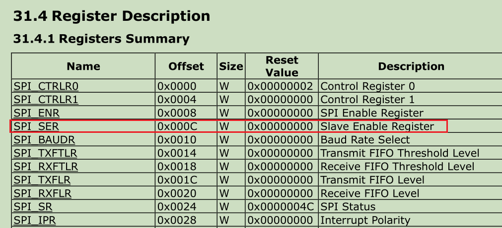
BIT(spi->chip_select)选择相应的位置1,其中spi->chip_select的赋值位置如下
static int of_spi_parse_dt(struct spi_controller *ctlr, struct spi_device *spi,
			   struct device_node *nc)
{
	u32 value;
	int rc;

	/* Mode (clock phase/polarity/etc.) */
	if (of_property_read_bool(nc, "spi-cpha"))
		spi->mode |= SPI_CPHA;
	if (of_property_read_bool(nc, "spi-cpol"))
		spi->mode |= SPI_CPOL;
	if (of_property_read_bool(nc, "spi-3wire"))
		spi->mode |= SPI_3WIRE;
	if (of_property_read_bool(nc, "spi-lsb-first"))
		spi->mode |= SPI_LSB_FIRST;
	if (of_property_read_bool(nc, "spi-cs-high"))
		spi->mode |= SPI_CS_HIGH;

.......
.......
	if (spi_controller_is_slave(ctlr)) {
		if (!of_node_name_eq(nc, "slave")) {
			dev_err(&ctlr->dev, "%pOF is not called 'slave'\n",
				nc);
			return -EINVAL;
		}
		return 0;
	}

	/* Device address */
	rc = of_property_read_u32(nc, "reg", &value);
	if (rc) {
		dev_err(&ctlr->dev, "%pOF has no valid 'reg' property (%d)\n",
			nc, rc);
		return rc;
	}
	spi->chip_select = value;

	/* Device speed */
	if (!of_property_read_u32(nc, "spi-max-frequency", &value))
		spi->max_speed_hz = value;

	return 0;
}
也就是读取设备树spi子节点的reg值
&spi4 {
	pinctrl-names = "default";
	pinctrl-0 = <&spi4m0_pins &spi4m0_cs1>;
	status = "okay";
	//cs-gpios = <&gpio1 RK_PC4 GPIO_ACTIVE_LOW>;
	spi@0{
			compatible = "microchip,mcp2518fd";
			reg = <0>;
			clocks = <&mcp2518_clk>;
			pinctrl-names = "default";
			pinctrl-0 = <&mcp2518_irq_pins>;
			spi-max-frequency = <20000000>;
			interrupts-extended = <&gpio1 RK_PA7 IRQ_TYPE_LEVEL_LOW>;
	};
};
spi绑定文档关于reg解释如下:选择相应的片选信号,所以这里reg是选择cs0还是cs1
.....
.....
   properties:
      compatible:
        description:
          Compatible of the SPI device.

      reg:
        minimum: 0
        maximum: 256
        description:
          Chip select used by the device.

      spi-3wire:
        $ref: /schemas/types.yaml#/definitions/flag
        description:
          The device requires 3-wire mode.

      spi-cpha:
        $ref: /schemas/types.yaml#/definitions/flag
        description:
          The device requires shifted clock phase (CPHA) mode
 ....
 ....
修改为reg = <1>;后片选能够正常拉低
片选能够正常拉低之后报错依旧和开始一样,识别不到从设备。查看2518的芯片手册可以看到输入引脚的电压范围为0.7倍的vdd到vdd+0.3,也就是2.3-2.6v。从上面的波形图中可以看到电压是不符合的。
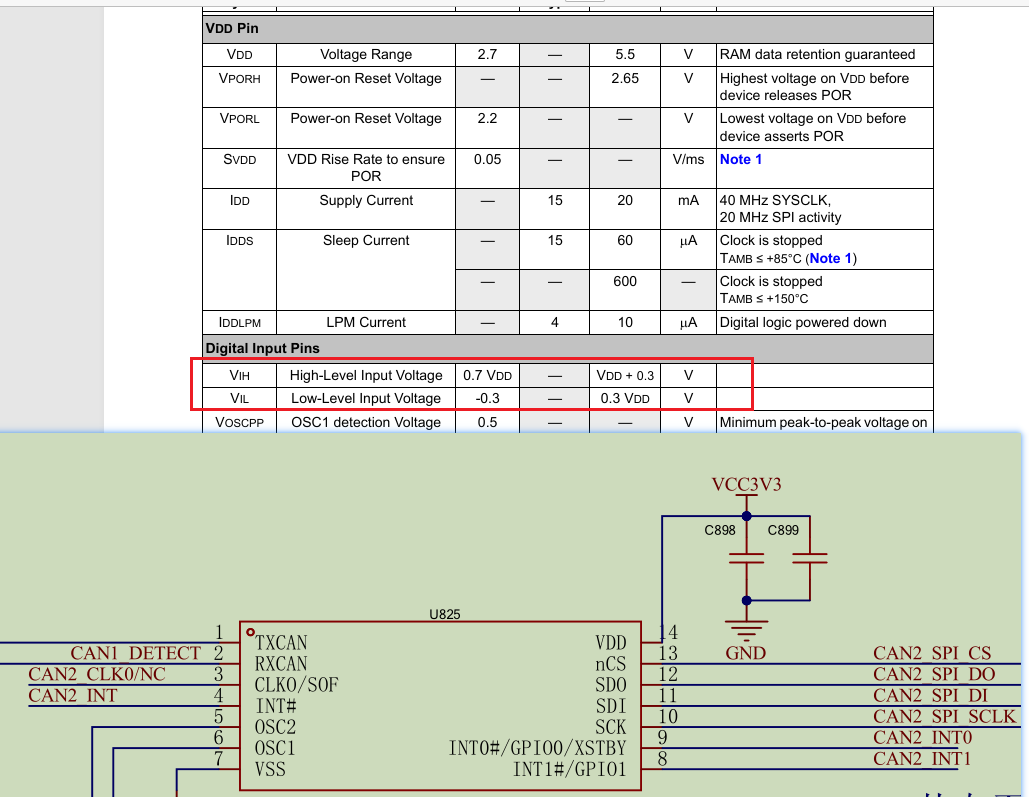
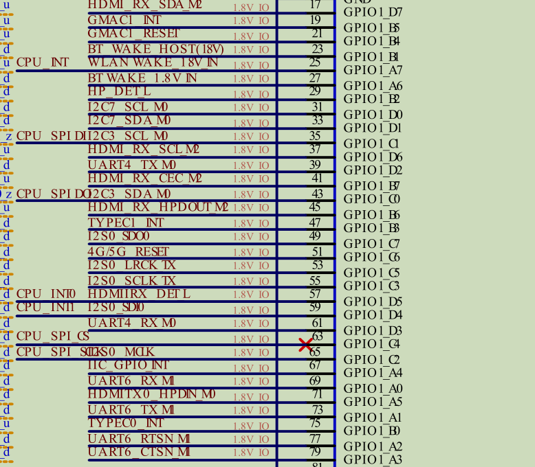
从原理中可以看到这些io都是1.8v的,所以这也是要注意的一点,有时候初始波形正确,但是通信却失败的时候可以查一查引脚的电压。有时候客户会做电压转换芯片,但是过了电压转换芯片可能也会有影响,低速信号可能影响不大,但是一些高速信号可能会导致信号不好从而引起时序问题,这需要看具体波形。

欢迎加入 MCP 技术社区!与志同道合者携手前行,一同解锁 MCP 技术的无限可能!
更多推荐
 4
4 0
0- 0


 已为社区贡献1条内容

所有评论(0)